Here is a list of examples on how to wire components, power supplies, connectors, sensors, etc to the WiFiG25 to create your own Linux embedded board. Click on the image of the device you want to add.


Power supply
The WiFiG25 needs a single line 5 volt DC power supply which can be provided in any combination on the following pins, only choose one method to power in the board:
| Position |
Pin Define |
Remarks |
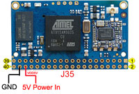
| J35 |
- Pin36 ----> +5V Power In
- Pin38 ----> GND
|
 |
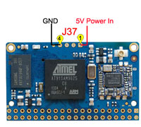
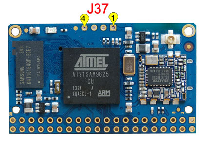
| J37 |
- Pin1 ----> +5V Power In
- Pin4 ----> GND
|
 |
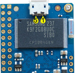
| Micro USB |
- Pin1 ----> +5V Power In
- Pin5 ----> GND
|
 |
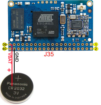
RTC backup battery
Applying 3 Volt DC on Pin38 (GND) and Pin39 (VBAT +3VDC) of the J35 connector it is possible to mantaint the RTC (Real Time Clock) active when the power supply if off. This will mantain the system clock up to 6 months with no power using a small CR1220 Lithium battery.
A bigger battery can be used to extend the time duration.
Debug Serial Port
The debug port is a special serial port used by the RomBOOT firmware burned inside the CPU ROM, the boot loader and the Linux Kernel loaded from the SD memory card to send the systems messages during their execution. The debug port is used also to have a low level access to the Linux system console.
The asyncronous serial signals are available on these pins:
| Pin # |
CPU Pin |
Primary |
Description |
--- |
Pin define on USB Seraial Cable |
|
| 1 |
VDD5V |
|
5V0 power in/out |
<--- |
Red line |
|
| 2 |
PA9 |
DRXD |
Debug serial port |
<--- |
Blue Line |
|
| 3 |
PA10 |
DTXD |
Debug serial port |
---> |
White Line |
|
| 4 |
GND |
|
Ground line |
<--- |
Black line |
|
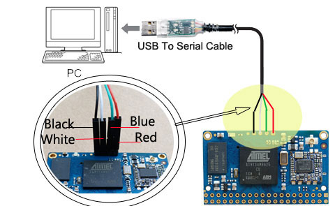 |
The VDD5V is the power in for the board, so you can use the USB serial cable to connect the board for debug and power supply the board.
USB Host
Up to 3 USB 2.0 host ports are available on WiFiG25 module:
- One hi-speed port at 480 Mbps for WiFi Module
- One full speed at 12 Mbps
- One of the hi-speed port can be used as device port.
The pin used are:
| WiFiG25 pins |
Port |
Description |
Mode |
J5[Pin27(D-), Pin25(D+)]
USB Micro(Pin2(D-), Pin3(D+)) |
Port A |
High Speed (480 Mbps) |
Host or Device |
| For WiFi Module used |
Port B |
High Speed (480 Mbps) |
Host |
| J5[Pin23 (D+), P24 (D-)] |
Port C |
Full Speed (12 Mbps) |
Host |
Here is a simple but working scheme.
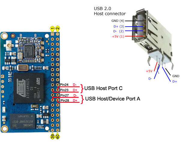
Please notice, the USB Host/Device Port A was configure as USB Device for default, if you want to use it as USB Device, you should configure it in linux kernel.
GPIO examples
Following is a simple example on how to wire a led or a push-button..
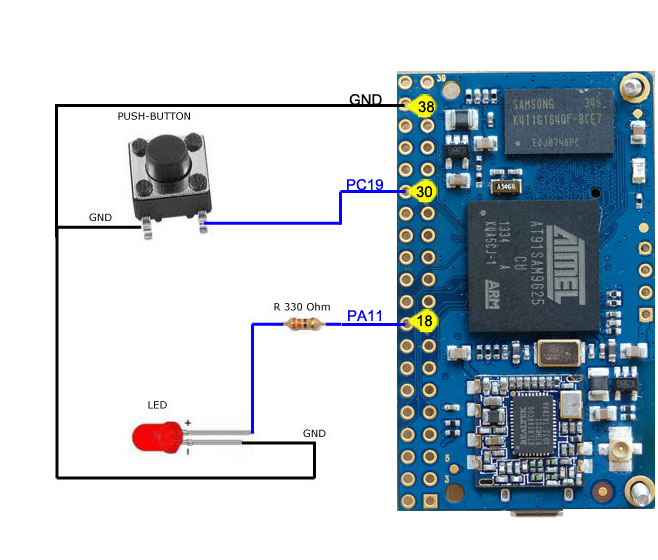
We used just two lines in this example but more lines are available and every one is configurable either in input or output mode: see the WiFIG25 pinout.
To learn how to drive the led or read the push-button state visit this article: GPIO lines.
All the lines are at 3.3 Volt. Do not connect any 5 Volt logic level signals to avoid damages.
 微博
微博
